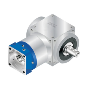
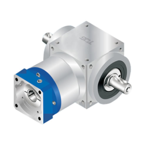
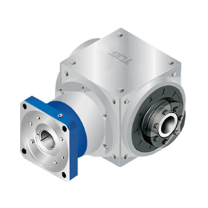
AT-FH Hole Output Flange Input Speed Reducer

Overview of AT-FH Steering Gearbox
- Hole output keyed configuration.
- Designed specially for servo motor and stepper motor.
- Various sizes and ratios for selection.
- Flange input type of planetary gearbox.
- High precision with low backlash.
- High output torque and high efficiency.
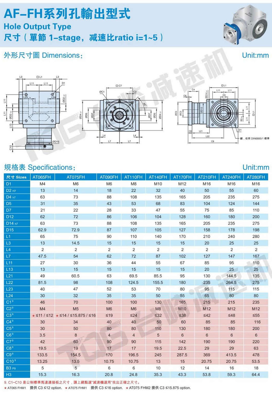
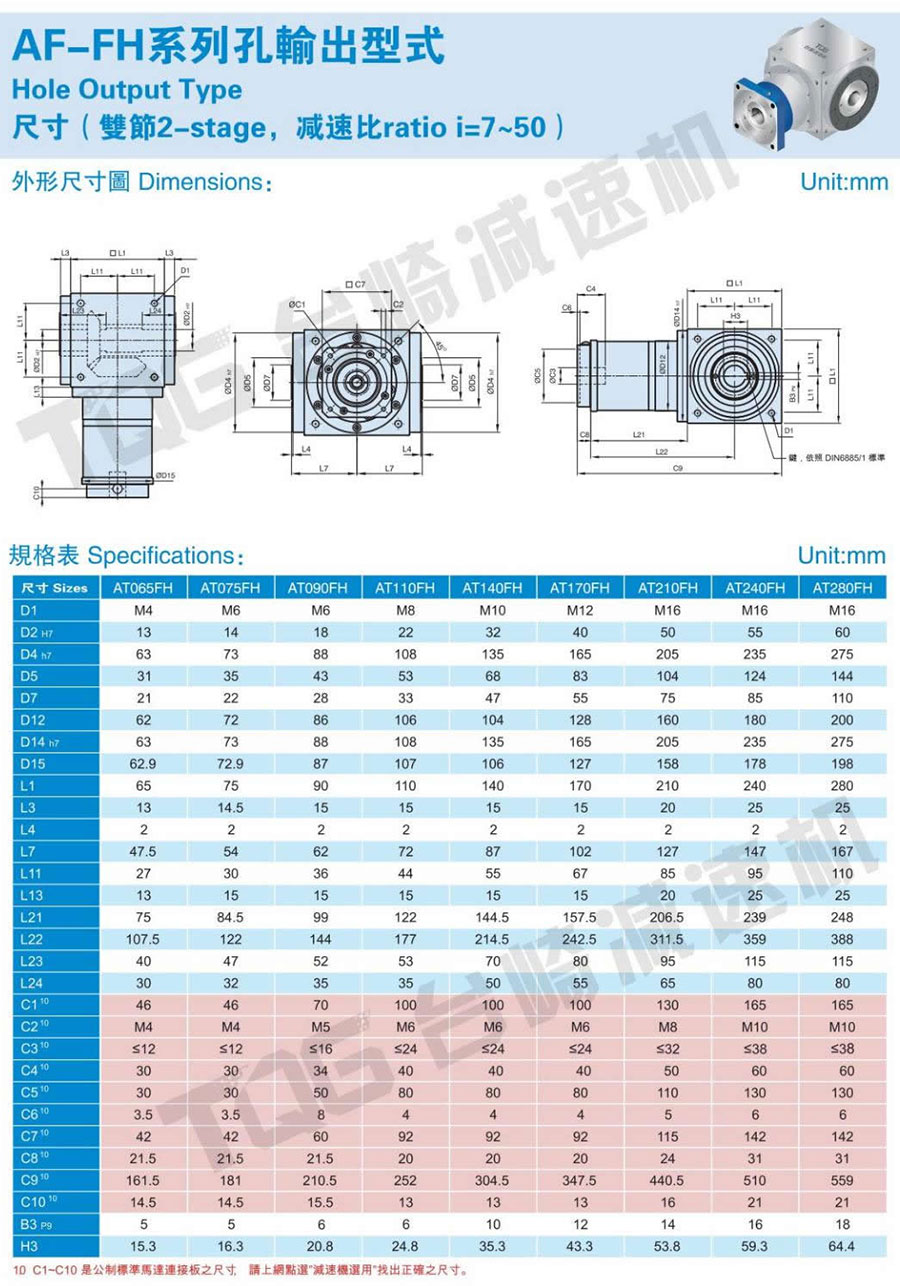
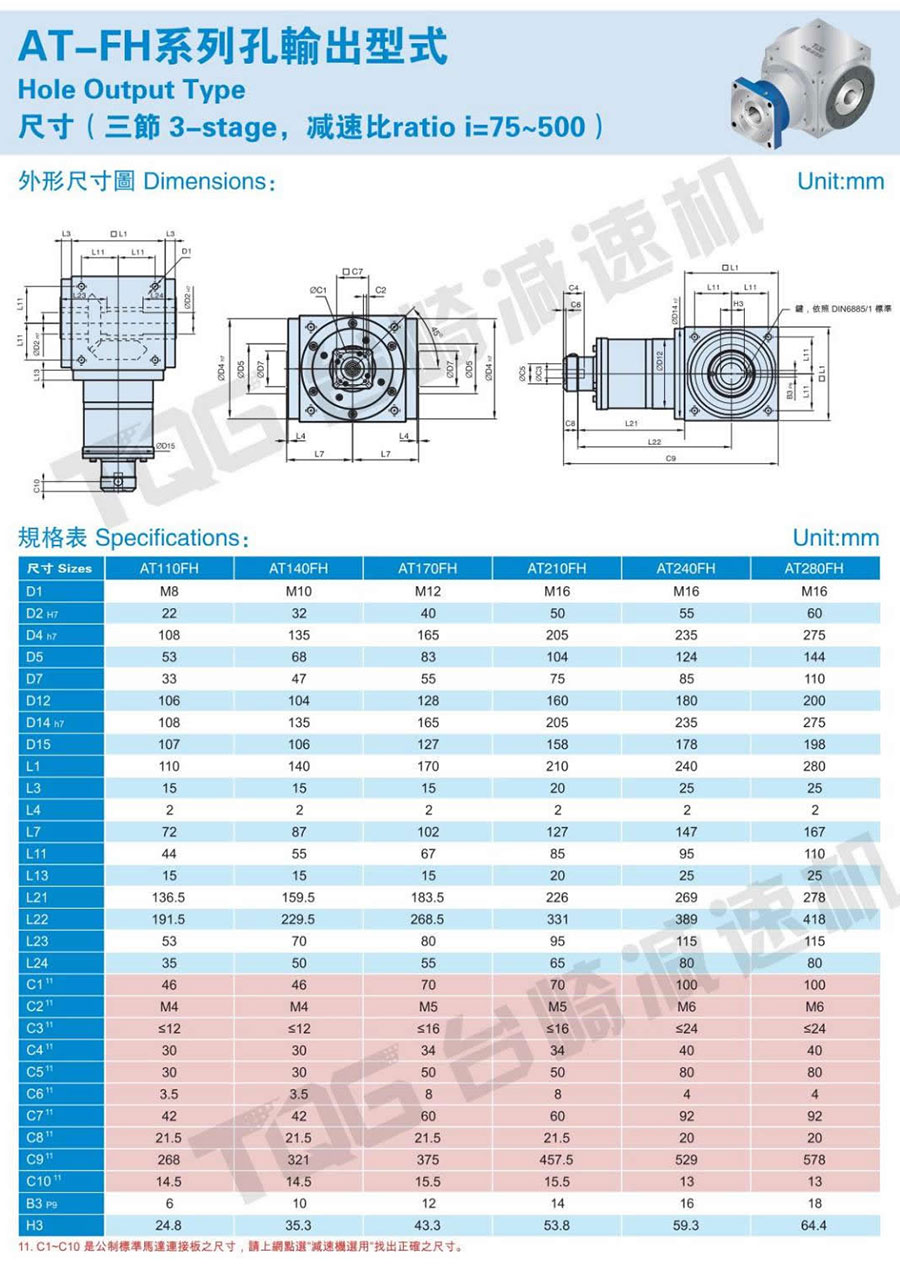
- 1 Stage with ratio of 1~5, 1-stage with ratio of 7~50, 3-stage with ratio of 75~500.
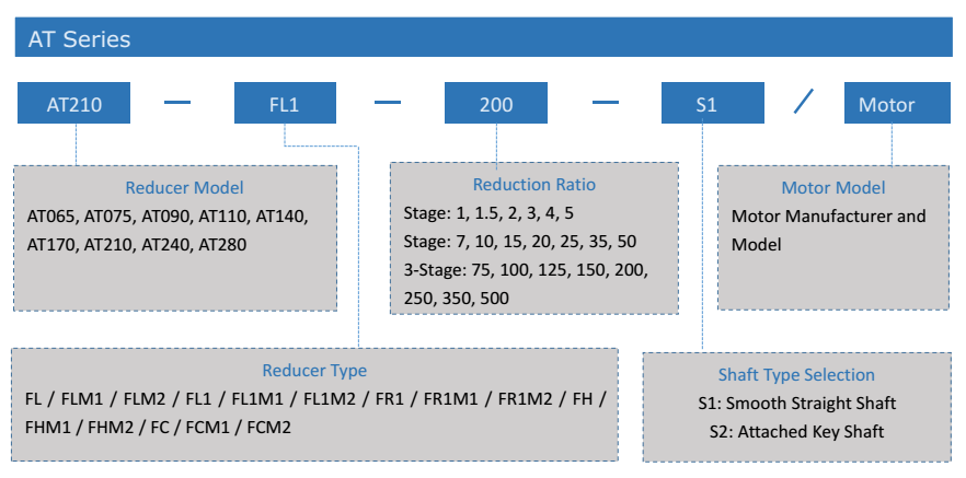
Indication of Model Numbers of AT-FH Steering Gearbox
Description of AT-FH Spiral Bevel Steering Gearbox
The TQG AT-FH series spiral bevel steering gearbox is a right angle servo gearbox with flange input and hollow keyed output configuration. It features of compact structure and light weight but with high radial load capacity. AT-FH helical reducers are widely used in servo applications and bring good solutions to our customers.
The TQG AT-FH steering gearboxes are widely applied in the following fileds: the walking shaft of a robot, gantry robot of machine tool, horizontal multi-joint robot, wafer handling robot, stamping equipment, pipe bending machines, injection mold taken-out robot, rotary tower knife frame rotation of machine tool, the xy anxis of machine tool, indexing table drive, roller drive for daubing use, pulley for loader use, shaft input belt drive, etc.
The Right Way to Install the AT Series Steering Gearbox
1.Confirm the specifications of the motor and speed reducer, and then clean the mounting surface of reducer and motor.
2.Take out of the buried bolts of the connecting plate and turn the motor locking device until the screws of the locking device are aligned with the hole of the buried bolts.
3. a. Remove the original key on the motor.
b. If necessary, please install the equilibrium bond.
4. Confirm the axis size of the motor, and install the shaft sleeve if necessary.
Note: The correct locking method: When the motor shaft is flat, align the bushing joints in the center line of the flat shaft, and make the locking hoop screw is vertical to the flat shaft.
5. Install the motor upright and lock tightly the screws that attached to gasket with the wrench according to the sequence from 1 to 4 with 5% of the torque value suggested in the Screw torque table ( Table 1)
.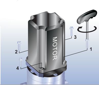
6. Set up the motor and the reducer upright, and lock tightly the screws of motor locking device with the wench according to the suggested torque in the table 2.
7.Set up the motor and the reducer upright and lock tightly the screws with the wrench according to the sequence from 1 to 4 with the torque value suggested in the Screw torque table ( Table 1).
8. Lock back to the buried bolt.
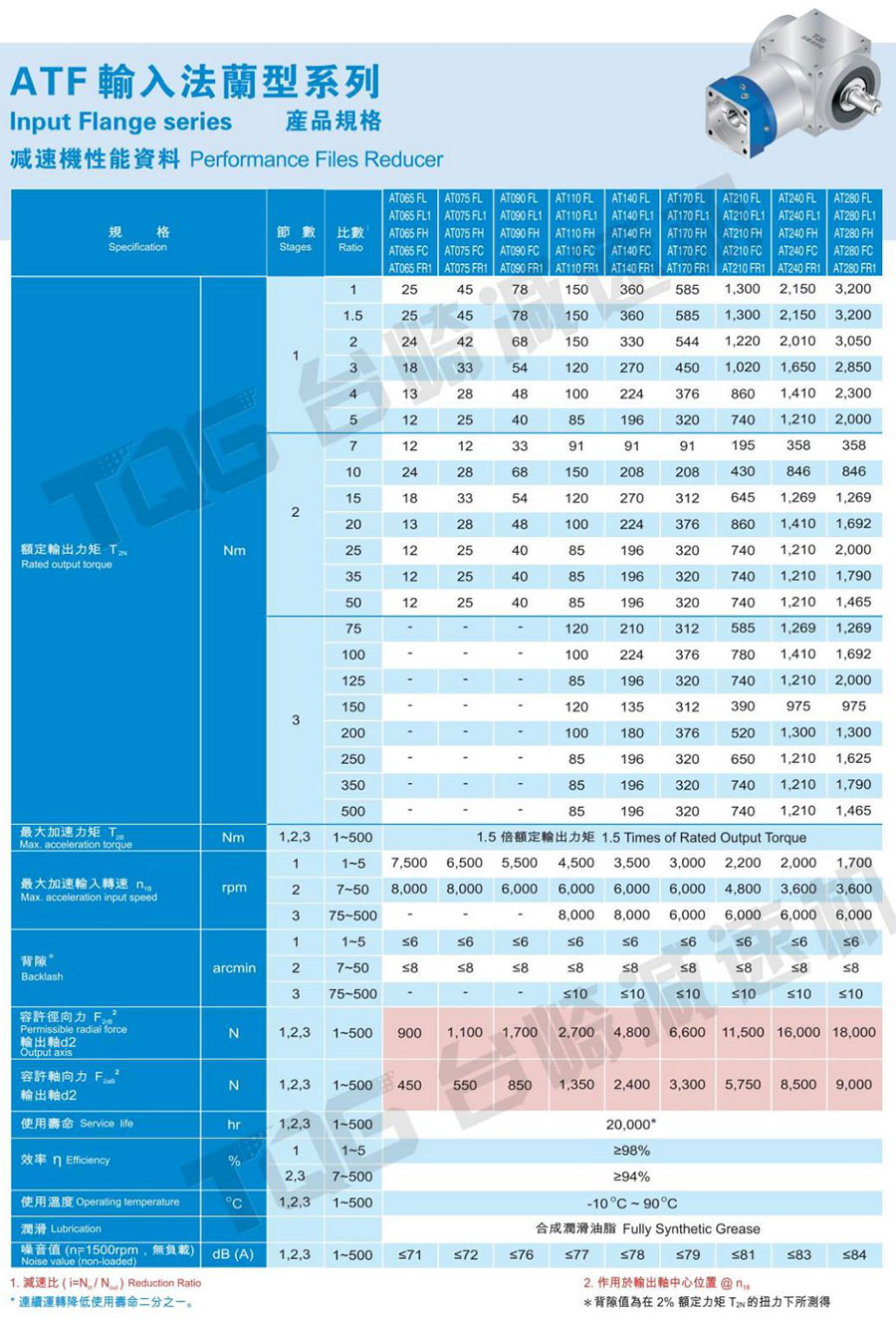
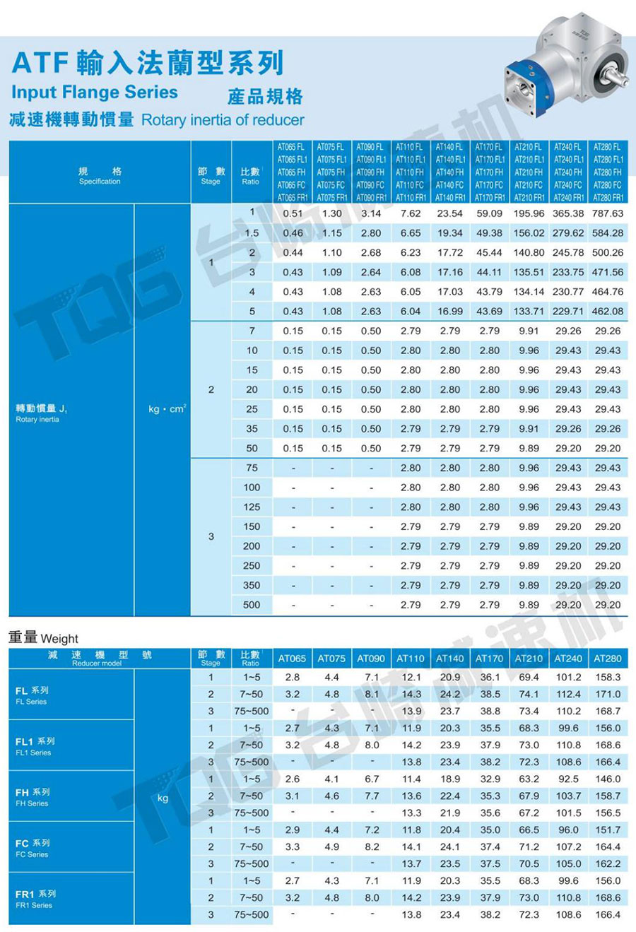
Specification Table of AT-FH Series
Catalogue of AT-FH Speed Reducer
—Download the complete catalog in the top navigation bar Click here to download